/* ---------------------------------------------------------------------------------------
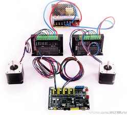
This optional dual axis feature is primarily for the homing cycle to locate two sides of
a dual-motor gantry independently, i.e. self-squaring. This requires an additional limit
switch for the cloned motor. To self square, both limit switches on the cloned axis must
be physically positioned to trigger when the gantry is square. Highly recommend keeping
the motors always enabled to ensure the gantry stays square with the $1=255 setting.
For Grbl on the Arduino Uno, the cloned axis limit switch must to be shared with and
wired with z-axis limit pin due to the lack of available pins. The homing cycle must home
the z-axis and cloned axis in different cycles, which is already the default config.
The dual axis feature works by cloning an axis step output onto another pair of step
and direction pins. The step pulse and direction of the cloned motor can be set
independently of the main axis motor. However to save precious flash and memory, this
dual axis feature must share the same settings (step/mm, max speed, acceleration) as the
parent motor. This is NOT a feature for an independent fourth axis. Only a motor clone.
WARNING: Make sure to test the directions of your dual axis motors! They must be setup
to move the same direction BEFORE running your first homing cycle or any long motion!
Motors moving in opposite directions can cause serious damage to your machine! Use this
dual axis feature at your own risk.
*/
// NOTE: This feature requires approximately 400 bytes of flash. Certain configurations can
// run out of flash to fit on an Arduino 328p/Uno. Only X and Y axes are supported. Variable
// spindle/laser mode IS supported, but only for one config option. Core XY, spindle direction
// pin, and M7 mist coolant are disabled/not supported.
// #define ENABLE_DUAL_AXIS // Default disabled. Uncomment to enable.
// Select the one axis to mirror another motor. Only X and Y axis is supported at this time.
#define DUAL_AXIS_SELECT X_AXIS // Must be either X_AXIS or Y_AXIS
// To prevent the homing cycle from racking the dual axis, when one limit triggers before the
// other due to switch failure or noise, the homing cycle will automatically abort if the second
// motor's limit switch does not trigger within the three distance parameters defined below.
// Axis length percent will automatically compute a fail distance as a percentage of the max
// travel of the other non-dual axis, i.e. if dual axis select is X_AXIS at 5.0%, then the fail
// distance will be computed as 5.0% of y-axis max travel. Fail distance max and min are the
// limits of how far or little a valid fail distance is.
#define DUAL_AXIS_HOMING_FAIL_AXIS_LENGTH_PERCENT 5.0 // Float (percent)
#define DUAL_AXIS_HOMING_FAIL_DISTANCE_MAX 25.0 // Float (mm)
#define DUAL_AXIS_HOMING_FAIL_DISTANCE_MIN 2.5 // Float (mm)
// Dual axis pin configuration currently supports two shields. Uncomment the shield you want,
// and comment out the other one(s).
// NOTE: Protoneer CNC Shield v3.51 has A.STP and A.DIR wired to pins A4 and A3 respectively.
// The variable spindle (i.e. laser mode) build option works and may be enabled or disabled.
// Coolant pin A3 is moved to D13, replacing spindle direction.
#define DUAL_AXIS_CONFIG_PROTONEER_V3_51 // Uncomment to select. Comment other configs.
// NOTE: Arduino CNC Shield Clone (Originally Protoneer v3.0) has A.STP and A.DIR wired to
// D12 and D13, respectively. With the limit pins and stepper enable pin on this same port,
// the spindle enable pin had to be moved and spindle direction pin deleted. The spindle
// enable pin now resides on A3, replacing coolant enable. Coolant enable is bumped over to
// pin A4. Spindle enable is used far more and this pin setup helps facilitate users to
// integrate this feature without arguably too much work.
// Variable spindle (i.e. laser mode) does NOT work with this shield as configured. While
// variable spindle technically can work with this shield, it requires too many changes for
// most user setups to accomodate. It would best be implemented by sharing all limit switches
// on pins D9/D10 (as [X1,Z]/[X2,Y] or [X,Y2]/[Y1,Z]), home each axis independently, and
// updating lots of code to ensure everything is running correctly.
// #define DUAL_AXIS_CONFIG_CNC_SHIELD_CLONE // Uncomment to select. Comment other configs


